Scratch 4 Arduino
From Vision - Multimedia Education
| |
Contents |
What is it ?
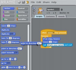
S4A is a Scratch modification that supports simple programming of the Arduino open source hardware platform. It provides new blocks for managing sensors and actuators connected to Arduino. There is also a sensor report board similar to the PicoBoard.
It has been created to attract people to the programming world. The goal is also to provide a high level interface to Arduino programmers with functionalities such as interacting with a set of boards through user events.
What is Scratch?
Scratch is a programming language thinked for initiate kids and youngsters in the world of programming. Its 100% Opensource. At the moment scratch is used arround the world.
The Programming language vinculated at the scratch interface its an imperative language with the fundamental syntaxisof programming, with a lot of instructions for make multimèdia projects, usually the scratch projects, are animationsor, games.
one of the most original things of the scratch is how u build, the code, the typical programming code, its "embed" in a construction blogs that u drag and drop for build phrases with sense, that works as a program, the syntax of the code is represented with the Shape of the blogs.
What is Arduino?
Arduino is a tool for making computers that can sense and control more of the physical world than your desktop computer. It's an open-source physical computing platform based on a simple microcontroller board, and a development environment for writing software for the board. Arduino can be used to develop interactive objects, taking inputs from a variety of switches or sensors, and controlling a variety of lights, motors, and other physical outputs. Arduino projects can be stand-alone, or they can be communicate with software running on your computer (e.g. Flash, Processing, MaxMSP.) The boards can be assembled by hand or purchased preassembled; the open-source IDE can be downloaded for free. The Arduino programming language is an implementation of Wiring, a similar physical computing platform, which is based on the Processing multimedia programming environment.
What can I do with it ?
Teach kids or youngsters to program and build his own toys or inventions.
Uses:
The uses are up to your imagination, but we present some exemples that can be replicated
Who can use this?
Anyone who its interested in electronics and want to teach
What do I Need ?
Requirements:
- A board of Arduino, there are different models, the most common are arduino uno
- One computer, with Linux, Windows, or Mac
- diferent electronic components, u can buy or just take it from old toys
How to download
- Scratch for arduino software: http://seaside.citilab.eu/scratch/arduino
- Arduino: http://arduino.cc/en/Main/Software (The drivers comes with the installer)
How to install
in the arduino homepage there is a guide for install the diferent models of arduino boards and for each O.S
http://arduino.cc/en/Guide/HomePage
Examples
we provide some examples of what can be done, but as we said they are just exemples, what u can do only its limited by imagination.
Example 1: Robot whit a remote controller
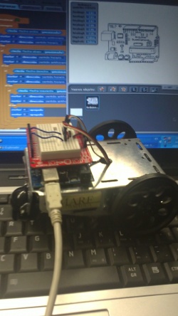
In this exemple we are going to explain how to build a robot made with one arduino board and two engines of continus rotation, controlled by another board with and acceleremeter, two leds and two botons
What we need?
Robot:
- 1 x Arduino board: http://www.sparkfun.com/products/9950
- 1 x protoshield: http://www.sparkfun.com/products/7914
- 1 x sticky board: http://www.sparkfun.com/products/7916
- 2 x servomotors Parallax Futaba continus rotation: http://www.parallax.com/Store/Accessories/MotorServos/tabid/163/CategoryID/57/List/0/Level/a/ProductID/102/Default.aspx?SortField=PboroductName,ProductName
- 1 x cable usb: http://www.sparkfun.com/products/512
Remote Controler:
- 1 x Arduino board: http://www.sparkfun.com/products/9950
- 1 x protoshield: http://www.sparkfun.com/products/7914
- 1 x sticky board: http://www.sparkfun.com/products/7916
- 1 x acceleremeter: http://www.sparkfun.com/products/849
- 2 x LEDS (of different colors, for example 1 red and 1 green): http://www.sparkfun.com/products/9590 (9590 red, 9592 green)
- 2 x switchers: http://www.sparkfun.com/products/97
- 1 x usb cable: http://www.sparkfun.com/products/512
How to do it?
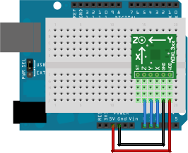
Before starting with the exercice, we are going to make some tests for see how work the engines and the accelerometer. In the first exemple we need to mount the accelerometer to the arduino board, using this model:
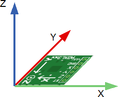
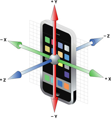
The Pins of the accelerometer for the power are GND and VDD, so we have to connect them to the board at GND and VDD at 5v. Pins Z, Y and X must be plugged at analogic 0, 1 and 2 respectly, This ones correspond to the three-dimensional coordinate axes ZYX (Z height, depth Y and X width) as you can see printed on it. The diagram below will clarify this concept:
A smartphone the accelerometer correspond to the following scheme:
The values given by the sensors of the accelerometer of every axis vary from 446 to 576 aproximatly. This means: If we take the board horitzontaly like we have it in the draw (leaving the Usb at Left, and Accelerometer at right)and we turn it clockwise 270 degrees (until usb its looking down and the accelerometer up) The y Axis will give us its minimum vale and should be above 446. if wereverse the movement, (USB above, accelerometer below), Will reach his maximum value and give us 576. The X axis will not have changed almost everything in this process, and if we had the board parallel to the ground, we will return a value of 511 roughly intermediate. Then a small theoretical calculation of this value:
576-446 = 130 130: 2 = 65 576-65 = 511 (or 446 + 65 = 511)
in the exercice the first thing to do its "calibrate" these values. so we gonna store these values in two variables. In this exercice we dont need the Z axis value. The calibration must be done with the board vertically, leaving the usb up and the accelerometer down.
Create two variables AxisY and AxisX for continusly store the values of axis y (analog 2) and axis X (analog 3. The value of Axis Y will have its minimum value. we subtract this value which gives about 0. We will do the same with the X axis subtracting the value intermediate, as will be parallel to the ground.
for what we need every Axis? As we know the cordinate system of scratch in regarding the direction of an object varies somewhat with respect to normal:
So we are gonna use the X axis for control the threshold 0, To know when switch between negative to positive and Y axis to vary the direction of the object.How does not match the value of the Y-axis accelerometer with the direction of the scratch, we must do a small conversion, that is, if we turn the board to the right we see that the variable Y takes a value About 65 (which it confirms the calculation we have done before), and Scratch the right equals 90, so:
90 / 65 = 1.384615385 (1.4 Rounding)
This is the factor that we use to pass the value of the Y axis in the direction Scratch. Please note that this factor is valid when the value of X axis is greater than 0, ie, when the board pointing to the right. If that points to the left, we will use the same factor but negative:
We also added a block to move the object.
Example 2: Robot Controled with keyboard
In the following example we will control the robot with the keyboard. The assemble scheme will be the following:
We need to connect each servo at (5V) and to the ground (GND) and one connected to the pin 4 and the other to the pin 7, they will recive the signal form the board and the program.
when we got it, we can start to program. first we have to create a new project, (File> New)put two blocs of motors and then we select the pins where we have it connected:
putting one in clockwise and the other counterclockwise and we start them making doble click on them, the robot should move forward (or backward depending of the order we plugged the servos). If we want to move it when we push a key we should do the follow:
(FOTO)
Now we have to do the same for the other keys, (changing the direction of each engine). And adding the Space Key for Stop the robot:
If we want the robot mobe when we push a key, and stop when we dont touch the keyboard we can do and alternative version:
Exemple 3: Robot Controlled with and accelerometer.
Now, we know how accelerometer and robot works, so we are ready for do the last exercice: Control the robot with the accelerometer.
The first we nees its add two switches (botons) to the accelerometer board, like this:
(foto)
One of these botos will serve for start and stop the robot, and the other for switch between forward and backward movement. Everyone require and a resistor of 10k acting as a pull down.
Now we can start to "Build" the program. We gonna start with the accelerometer board. The first step will be calibrate the acclerometer, like we did in the first exemple, but this time the only axis we need its X. How we got it plugged at Analogic pin 2 we gonna use analog 3. And we create a new Variable, (for all the other objects, because we gonna need to see them from arduino obect) where we gonna store the X axis value calibrated:
(FOTO)
This Variable "Direction" will give us 0, aproximatly, when we got the board vertically with the usb cable pointed up.
The next step its do another bloc of instruccions.-.-.-.-.-.-.-.-.-.-.-.-.-.-.-.-.-.-.-.-.-.-.-.-.-.-.-.-.-.-.-.-.-.-.-.-.-.
A continuació farem un altre bloc d’instruccions amb el que control·larem l’estat dels botons. Crearem un parell de variables més (només per aquest objecte) per a guardar l’estat dels botons. També crearem dos variables més, una per saber quan estarà engegat o aturat el robot (motorsOn) i l’altra per control·lar el moviment cap a endavant i cap enrere (moveForward). Aquestes últimes han de ser per a tots els objectes.
Ara bé, el fet de fer servir botons ens planteja una qüestió: per exemple, en el cas del que controlarà el moviment endavant i enrere, volem que canvii de sentit només quan premem el botó o que continui fins que li donem un altre cop? Evidentment la segona opció és la més pràctica (i també la més complicada, encara que no gaire). Per tant, farem que es mogui només quan detecti el moment en que premem el botó, és a dir, si passem de l’estat no premut (false) a premut (true). A més haurem d’actualitzar l’estat del botó segons si està premut el botó o no:
D’aquesta manera si premem el botó i el mantenim premut, només entrará un cop al condicional, ja que quan surt d’aquest asigna el valor de Digital1 (true) a la variable button1State, i quan repeteix el bucle no es compleix la condició ja que button1State serà true i no false. Ara queda afegir que farà:
Ara quan entri al condicional, mirarà el valor de la variable moveForward. En cas de que sigui true el canviarà a false, i viceversa. Per tant cada cop que premem el botó canviará d’un sentit a l’altre. Fem lo mateix amb el botó d’engegat i la variable motorsOn i ho ajuntem amb lo que tenim:
Ara només queda inicialitzar les variables i ja tindrem llesta la part de la placa amb l’acceleròmetre:
A continuació crearem un nou objecte Arduino per al robot. Aquí l’únic que farem serà comprovar el valor de les variables motorsOn, moveForward i direction i actuar en conseqüència. Per exemple, si la variable motorsOn està a false vol dir que el robot està parat. En cas contrari voldrà dir que s’ha de moure:
I que hem de fer quan els motors són en marxa? Dirigir-los segons les variables moveForward i direction. Amb aquesta última hem de decidir un valor llindar per saber quan hem de girar a dreta, a esquerra o anar tot recte (per exemple podem fer servir un valor de 40 aproximadament). Llavors tindrem 3 casos: si direction és menor de -40: girarem cap a l’esquerra. si direction és major de 40: girarem cap a la dreta. si no es compleix cap de les dos anteriors (és a dir, direction es troba entre -40 i 40): anar recte.
Abans de començar hem d’estipular quina és la part davantera i la posterior del robot, per tal de saber quan anirà cap endavant o cap enrera i quin serà el motor esquerre i quin el dret. En el nostre cas ho hem dissenyat d’aquesta manera:
El motor esquerre estarà connectar al pin 4 i el dret al 7. A continuació tenim una taula que resumeix en quin sentit han d’anar els motors depenent del valor de direction en el cas de que el robot vagi cap endavant, és a dir, quan és compleix que moveForward és true:
valor de direction tipus de moviment motor esquerre (pin 4) motor dret (pin 7)
menor de -40 girar cap a l’esquerra horari horari
major de 40 girar cap a la dreta antihorari antihorari
entre -40 i 40 anar recte antihorari horari
I en el cas de que moveForward sigui false, és el mateix però invertit:
valor de direction tipus de moviment motor esquerre (pin 4) motor dret (pin 7) menor de -40 girar cap a l’esquerra antihorari antihorari major de 40 girar cap a la dreta horari horari entre -40 i 40 anar recte horari antihorari
Ara només ens queda aplicar-ho al nostre programa:
I afegir-ho a lo que ja teníem fet:
I això és tot! Enjoy! :)
Example 2: Kandinsky instrument
This one its a little musicbox that works playing notes, depending in how u put ur hand.
What we need?
- 1 x Arduino board: http://www.sparkfun.com/products/9950
- 1 x InfraRed Sensor: http://www.sparkfun.com/products/7914
- 1 x sticky board: http://www.sparkfun.com/products/7916
- 1 x cable usb: http://www.sparkfun.com/products/512
- 1 x protoshield: http://www.sparkfun.com/products/7914
- 1 x LED RGB: http://www.sparkfun.com/products/105
- 3 x Resistors 220 ohms http://www.sparkfun.com/products/
- 1 x usb cable: http://www.sparkfun.com/products/512
How to do it?
What´s more?
Useful information?
- It could be connecte to another profile dedicated to organitzations.
