Scratch 4 Arduino
From Vision - Multimedia Education
| (71 intermediate revisions not shown) | |||
| Line 1: | Line 1: | ||
| - | + | {{Scratch 4 Arduino}} | |
| - | + | {| align="right" | |
| + | | __TOC__ | ||
| + | |} | ||
| - | + | <br/>''This Translation its in WIP state, need some revisions and things to finish :)'' | |
| - | = | + | =What is it?= |
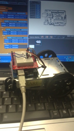
| + | [[Image:S4ahardsoft.JPG|thumb|right|250px]] S4A is a Scratch modification that supports simple programming of the Arduino open source hardware platform. It provides new blocks for managing sensors and actuators connected to Arduino. There is also a sensor report board similar to the PicoBoard. | ||
| - | + | It has been created to attract people to the programming world. The goal is also to provide a high level interface to Arduino programmers with functionalities such as interacting with a set of boards through user events. | |
| + | === What is Scratch? === | ||
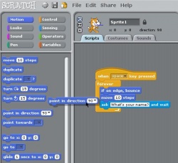
| - | + | Scratch is an opensource programming environment oriented for initiate kids and youngsters in the world of programming. The programming language vinculated at Scratch’s interface it’s a simple language with the fundamental syntaxis of programming, with a lot of instructions (embedded in blocks) for make multimedia projects, like animations or games. You can drag and drop these blocks for build your program like a puzzle. | |
| - | + | <br/>[[Image:Scracth code.JPG|thumb|left|250px]] | |
| - | + | ||
| - | + | ||
| - | === What | + | === What is Arduino? === |
| - | + | Arduino is a tool for making computers that can sense and control more of the physical world than your desktop computer. It's an open-source physical computing platform based on a simple microcontroller board, and a development environment for writing software for the board. Arduino can be used to develop interactive objects, taking inputs from a variety of switches or sensors, and controlling a variety of lights, motors, and other physical outputs. Arduino projects can be stand-alone, or they can be communicate with software running on your computer (e.g. Flash, Processing, MaxMSP.) The boards can be assembled by hand or purchased preassembled; the open-source IDE can be downloaded for free. The Arduino programming language is an implementation of Wiring, a similar physical computing platform, which is based on the Processing multimedia programming environment. | |
| - | <br/><br/> | + | |
| + | = What can I do with it ? = | ||
| + | |||
| + | *Promove kids or youngsters to program and build his own inventions. | ||
| + | *Teach programming to anyone in a funny and easy way. | ||
| + | *Learn the basics of electronics. | ||
| + | *Make an introduction to Arduino, to people who didn’t have any contact with electronics or computer programming world. | ||
| + | |||
| + | =What can we do with it?= | ||
| + | |||
| + | == Uses: == | ||
| + | *The uses are up to your imagination, but here are some examples that we used and you can replicate. | ||
| + | |||
| + | = Who can use this? = | ||
| + | *Anyone interested of electronics or programming and want to learn more or teach. | ||
| + | |||
| + | = What do I need ? = | ||
| + | *An Arduino board, we have tested Diecimila, Duemilanove and Uno (this last is the newest). | ||
| + | *A computer, with Linux, Windows or Mac. | ||
| + | *Some electronic or robotic components, that you can buy or just save from old toys or electronic devices. | ||
| + | |||
| + | == Requirements: == | ||
| + | |||
| + | *Basic knowledge of Arduino and of the electronic components you are going to use, although you can find how to connect them to the board or what they need to work at this URL: http://arduino.cc/en/Tutorial/HomePage. | ||
| + | *All information and schematics about how to connect and work with all the basic components, like switches, leds, infrared sensors, servos, etc, is also there. | ||
| + | |||
| + | == How to download == | ||
| + | *Scratch 4 Arduino (software and firmware): http://seaside.citilab.eu/scratch/arduino | ||
| + | *Arduino IDE: http://arduino.cc/en/Main/Software (the drivers come with the installer) | ||
| + | |||
| + | == How to install == | ||
| + | |||
| + | *At the website of Arduino there is a guide to start working with any of the different boards besides how to install the IDE for each OS: http://arduino.cc/en/Guide/HomePage | ||
| + | |||
| + | |||
| + | = What can we do with it? = | ||
| + | |||
| + | ==Examples== | ||
| + | *We provide some examples of what can be done, but as we said they are just examples, what you can do only it's limited by imagination. | ||
| + | |||
| + | === [[Example 1: Robot with a remote controller]] === | ||
| + | In this example we will explain how to build a robot made with an Arduino board and two continuos rotation servomotors, controlled by another board with an accelerometer, two leds and two buttons. | ||
| + | |||
| + | ==== What do we need? ==== | ||
| + | |||
| + | '''Robot:''' | ||
| + | |||
| + | *1 x Arduino board: http://www.sparkfun.com/products/9950 | ||
| + | *1 x protoshield: http://www.sparkfun.com/products/7914 | ||
| + | *1 x sticky board: http://www.sparkfun.com/products/7916 | ||
| + | *2 x continuous rotation servomotors (Parallax Futaba): http://www.parallax.com/Store/Accessories/MotorServos/tabid/163/CategoryID/57/List/0/Level/a/ProductID/102/Default.aspx?SortField=PboroductName,ProductName | ||
| + | *1 x USB cable: http://www.sparkfun.com/products/512 | ||
| + | |||
| + | <br/>'''Remote Controler:''' | ||
| + | |||
| + | *1 x Arduino board: http://www.sparkfun.com/products/9950 | ||
| + | *1 x protoshield: http://www.sparkfun.com/products/7914 | ||
| + | *1 x sticky board: http://www.sparkfun.com/products/7916 | ||
| + | *1 x acceleremeter: http://www.sparkfun.com/products/849 | ||
| + | *2 x LEDS (of different colors, for example 1 red and 1 green): http://www.sparkfun.com/products/9590 (9590 red, 9592 green) | ||
| + | *2 x switchers: http://www.sparkfun.com/products/97 | ||
| + | *1 x USB cable: http://www.sparkfun.com/products/512 | ||
| + | |||
| + | ==== How to do it? ==== | ||
| + | |||
| + | Before start the exercise we will make some tests to see how servos and accelerometer work. In the first example, we need to plug the accelerometer to the Arduino board, using this scheme: | ||
| + | |||
| + | <br/>[[Image:Accelerometer bb.png|center|Accelerometer bb.png]] | ||
| + | |||
| + | <br/>The pins of the accelerometer for power are GND and VDD, so we have to connect them to the board at GND and VDD at 5V. Pins Z, Y and X must be plugged at analog 0, 1 and 2 respectively. These ones correspond to the three-dimensional coordinate axes ZYX (Z height, Y depth and X width) as you can see printed on it. The diagram below will clarify this concept: | ||
| + | |||
| + | <br/>[[Image:Acelerometro ejes.png|center|Acelerometro ejes.png]] | ||
| + | |||
| + | <br/>The values given by the sensors of the accelerometer of every axis vary from 446 to 576 aprox. This means: if we take the board horitzontally like we have it in the previous scheme (leaving the USB jack at left, and the accelerometer at right) and we turn it clockwise 90 degrees (until jack its looking up and the accelerometer down) the Y axis give us its minimum vale and should be above 446. If we reverse the movement (jack down, accelerometer up) it reaches his maximum value and give us 576 aprox. The X axis did not changed almost in this process, and if the board is parallel to the ground, it will give us a value of 511 aprox. Next we have a little theoretical calculation of this value: | ||
| + | |||
| + | <br/>''576-446 = 130'' | ||
| + | |||
| + | ''130: 2 = 65'' | ||
| + | |||
| + | '''576-65 = 511 (or 446 + 65 = 511)''' | ||
| + | |||
| + | <br/>In the exercise the first thing to do it's "calibrate" these values, so we gonna store these values in two variables. In this exercise we don't need the Z axis value. The calibration must be done with the board vertically, leaving the USB up and the accelerometer down. | ||
| + | |||
| + | <br/>[[Image:Sa1.PNG|center|Sa1.PNG]] | ||
| + | |||
| + | <br/>We need to create two variables (yAxis and xAxis) to store the values of Y axis (analog 2) and X axis (analog 3). Y axis will reach its minimum value (446), <span id="result_box" class="short_text" lang="en"><span title="Haz clic para obtener otras posibles traducciones" class="hps">so</span> <span title="Haz clic para obtener otras posibles traducciones" class="hps">this</span> <span title="Haz clic para obtener otras posibles traducciones" class="hps">will be</span> <span title="Haz clic para obtener otras posibles traducciones" class="hps">the value</span> <span title="Haz clic para obtener otras posibles traducciones" class="hps">to</span> <span title="Haz clic para obtener otras posibles traducciones" class="hps">subtract</span></span>. We will do the same in the X axis subtracting the value intermediate (511), as will be parallel to the ground. | ||
| + | |||
| + | For what we need every axis? As we know the coordinate system of Scratch in regarding the direction of an object varies somewhat with respect to normal: | ||
| + | |||
| + | <br/>[[Image:PCS.png|center|PCS.png]] | ||
| + | |||
| + | <br/>So we are gonna use the X axis tocontrol the threshold 0, to know when switch between negative to positive and Y axis to vary the direction of the object. As the value of the Y axis does not match with the direction of a Scratch object, we must do a small conversion: if we turn the board to the right we see that the variable Y takes a value About 65 (which it confirms the calculation we have done before) and in Scratch right equals 90, so: | ||
| + | |||
| + | <br/>'''90 / 65 = 1.384615385 (1.4 rounding up)''' | ||
| + | |||
| + | <br/>This is the factor that we use to pass the value of the Y axis in the direction of Scratch. Please note that this factor is valid when the value of X axis is greater than 0, ie, when the board pointing to the right. If that points to the left, we will use the same factor but negative: | ||
| + | |||
| + | <br/>[[Image:S4a02.png|center|S4a02.png]] | ||
| + | |||
| + | <br/>We also added a block to move the object. | ||
| + | |||
| + | <br/>'''Example 2: Robot Controled with keyboard''' | ||
| + | |||
| + | In the following example we will control the robot with the keyboard. The assemble scheme will be the following: | ||
| + | |||
| + | <br/>[[Image:Servomotors bb.png|center|Servomotors bb.png]] | ||
| + | |||
| + | <br/>We need to connect each servo at (5V) and to the ground (GND) and one connected to the pin 4 and the other to the pin 7, they will recive the signal form the board and the program. | ||
| + | |||
| + | When we got it, we can start to program. first we have to create a new project, (File> New)put two blocs of motors and then we select the pins where we have it connected: | ||
| + | |||
| + | <br/>[[Image:Sers4a.png|center|Sers4a.png]] | ||
| + | |||
| + | <br/>Putting one in clockwise and the other counterclockwise and we start them making doble click on them, the robot should move forward (or backward depending of the order we plugged the servos). If we want to move it when we push a key we should do the follow: | ||
| + | |||
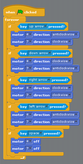
| + | <br/>[[Image:S4a03.png|center|S4a03.png]] | ||
| + | |||
| + | <br/>Now we have to do the same for the other keys, (changing the direction of each engine). And adding the Space Key for Stop the robot: | ||
| + | |||
| + | <br/>[[Image:S4a04.png|center|S4a04.png]] | ||
| + | |||
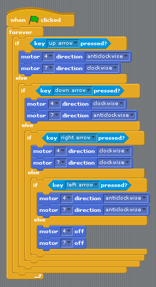
| + | <br/>If we want the robot move when we push a key, and stop when we don't touch the keyboard we can do and alternative version: | ||
| + | |||
| + | <br/>[[Image:S4a05.png|center|S4a05.png]] | ||
| + | |||
| + | <br/>'''Example 3: Robot Controlled with and accelerometer''' | ||
| + | |||
| + | Now, we know how accelerometer and robot works, so we are ready for do the last exercice: Control the robot with the accelerometer. | ||
| + | |||
| + | The first we need its add two switches (botons) to the accelerometer board, like this: | ||
| + | |||
| + | <br/>[[Image:Acceler.png|center|Acceler.png]] | ||
| + | |||
| + | <br/>One of these switch it's for start and stop the robot, and the other for switch between forward and backward movement. Everyone requires a resistor of 10k acting as a pull down. | ||
| + | |||
| + | Now we can start to "Build" the program. We gonna start with the accelerometer board. The first step will be calibrate the acclerometer, like we did in the first exemple, but this time the only axis we need its X. How we got it plugged at Analogic pin 2 we gonna use analog 3. And we create a new Variable, (for all the other objects, because we gonna need to see them from arduino obect) where we gonna store the X axis value calibrated: | ||
| + | |||
| + | <br/>[[Image:S4a06.png|center|S4a06.png]] | ||
| + | |||
| + | <br/>This variable "direction" will give us 0, aproximately, when we got the board vertically with the usb cable pointed up. | ||
| + | |||
| + | The next step its create another bloc of instruccions for control the state of the bottons; We will create a few variables (only for this Object) to keep the button state. Also create two variables, one to know when the robot is started or stopped (motorsOn) and one for controlling the movement forward and backward (moveForward). The latter must be for all objects. | ||
| + | |||
| + | But the fact of using buttons raises a question: for example, in the case that control the movement forward or backward, we want to change direction only when you press the button or you continue until you give again? Obviously the second option is more practical (and also more complicated, though not much). Therefore, we will move only when it detects when you press the button, that is, if we were not pressed the (false) to down (true). In addition we will update the status of the button depending on whether or not the button is pressed: | ||
| + | |||
| + | <br/>[[Image:S4a07.png|center|S4a07.png]] | ||
| + | |||
| + | <br/>''By this way if u press and hold the button, only goes one time to the conditional.'' because when it comes out, assing the value Digital1 (true) button1State to the variable, and repeats the loop when the condition is not met button1State as is true and not false. Now you should add what the condition has to do: | ||
| + | |||
| + | <br/>[[Image:S4a08.png|center|S4a08.png]] | ||
| + | |||
| + | <br/>Now when it comes to conditional, will look the value of the variable moveForward. In case of that is true it will change to false and vice versa. So every time you press the button will shift from one sense to another. We do the same with the power button and the variable motorsOn and put it together with what we have: | ||
| + | |||
| + | <br/>[[Image:S4a09.png|center|S4a09.png]] | ||
| + | |||
| + | <br/>Now all that remains is initialize the variables and we will have the board with the accelerometer: | ||
| + | |||
| + | <br/>[[Image:S4a10.png|center|S4a10.png]] | ||
| + | |||
| + | <br/>The following is create a new Arduino object for the robot. Here all you do is check the value of the variables motorsOn, moveForward and direction and act accordingly. For example, if the variable motorsOn is false means that the robot is stationary. Otherwise it means to be moved: | ||
| + | |||
| + | <br/>[[Image:S4a11.png|center|S4a11.png]] | ||
| + | |||
| + | <br/>And what we have to do when the engines are running? Directing them as the variables moveForward and direction. With the latter we choose one threshold value to know when we turn right, left or go straight ahead (for example we can use one value of 40 approximately). Then we will have three cases: | ||
| + | |||
| + | <br/>'''if direction is less than -40: turn left.''' | ||
| + | |||
| + | '''if direction is greater than 40: turn right.''' | ||
| + | |||
| + | '''if not met any of the previous two (ie, direction is between -40 and 40): go straight.''' | ||
| + | |||
| + | <br/>Before starting we must stipulate what is the front and back of the robot to know when to go forward or back and what engine is for the right and wich is for left. In our case we designed this way: | ||
| + | |||
| + | <br/>[[Image:Servomotors2 bb.png|center|Servomotors2 bb.png]] | ||
| + | |||
| + | <br/>The left engine is connected to pin 4 and right engine at pin 7. Below we have a table that summarizes in what sense should be the engines depending on the value of and direction in the case of the robot go forward, that is, when it meets moveForward is true: | ||
| + | |||
| + | |||
| + | |||
| + | {| style="width: 600px; height: 200px" align="center" border="1" | ||
| + | |- | ||
| + | | style="text-align: center" | '''value of direction''' | ||
| + | | style="text-align: center" | '''type of movement''' | ||
| + | | style="text-align: center" | '''left servo (pin 4)''' | ||
| + | | style="text-align: center" | '''right servo (pin 7)''' | ||
| + | |- | ||
| + | | style="text-align: center" | ''less than -40'' | ||
| + | | style="text-align: center" | turn left | ||
| + | | style="text-align: center" | clockwise | ||
| + | | style="text-align: center" | clockwise | ||
| + | |- | ||
| + | | style="text-align: center" | ''more than -40'' | ||
| + | | style="text-align: center" | turn right | ||
| + | | style="text-align: center" | anticlockwise | ||
| + | | style="text-align: center" | anticlockwise | ||
| + | |- | ||
| + | | style="text-align: center" | ''between -40 and 40'' | ||
| + | | style="text-align: center" | go forward | ||
| + | | style="text-align: center" | anticlockwise | ||
| + | | style="text-align: center" | clockwise | ||
| + | |} | ||
| + | |||
| + | <br/>In the case of "moveForward" its false, its the same but reversed: | ||
| + | |||
| + | |||
| + | |||
| + | {| style="width: 600px; height: 200px" align="center" border="1" | ||
| + | |- | ||
| + | | style="text-align: center" | '''value of direction''' | ||
| + | | style="text-align: center" | '''type of movement''' | ||
| + | | style="text-align: center" | '''left servo (pin 4)''' | ||
| + | | style="text-align: center" | '''right servo (pin 7)''' | ||
| + | |- | ||
| + | | style="text-align: center" | ''less than -40'' | ||
| + | | style="text-align: center" | turn left | ||
| + | | style="text-align: center" | anticlockwise | ||
| + | | style="text-align: center" | anticlockwise | ||
| + | |- | ||
| + | | style="text-align: center" | ''more than -40'' | ||
| + | | style="text-align: center" | turn right | ||
| + | | style="text-align: center" | clockwise | ||
| + | | style="text-align: center" | clockwise | ||
| + | |- | ||
| + | | style="text-align: center" | ''between -40 and 40'' | ||
| + | | style="text-align: center" | go forward | ||
| + | | style="text-align: center" | clockwise | ||
| + | | style="text-align: center" | anticlockwise | ||
| + | |} | ||
| + | |||
| + | <br/>Now the only thing to do its apply that to our program: | ||
| + | |||
| + | <br/>[[Image:S4a12.png|center|S4a12.png]] | ||
| + | |||
| + | <br/>And add it to what we had done: | ||
| + | |||
| + | <br/>[[Image:S4a13.PNG|center|S4a13.PNG]] | ||
| + | |||
| + | <br/>Enjoy! :) | ||
| + | |||
| + | |||
| + | |||
| + | === [[Example 2: Script music workshop (Kandinsky)]] === | ||
| + | |||
| + | Needed components: | ||
| + | |||
| + | 1 x Arduino board: http://www.sparkfun.com/products/9950 | ||
| + | |||
| + | 1 x Sensor infrared SHARP GP2Y0A21YK: http://www.sparkfun.com/products/242 | ||
| + | |||
| + | 1 x LED RGB: http://www.sparkfun.com/products/105 | ||
| + | |||
| + | 1 x usb cable: http://www.sparkfun.com/products/512 | ||
| + | |||
| + | <br/>'''Step 1: Playing notes with the sensor''' | ||
| + | |||
| + | Before anything else Create an Arduino object (or take what comes by default at the beginnig of new project), which set one number to a variable depending on the value of the sensor | ||
| + | |||
| + | <br/>[[Image:Selección 001.png|center|Selección 001.png]] | ||
| + | |||
| + | <br/>How we have to constantly monitor the value of the sensor we will use one endless loop where each iteraction store the value of the sensor into a variable. Depending on the value and if exceed or not certain thresholds, the variable will have one value or another value (from 1 to 7). In case of it is less than 160 (that is, if the sensor does not detect any obstacle) consider one value of 0. Note: The variable value must be visible to all items! | ||
| + | |||
| + | We will create another Object that will be the main program. What what we have to do first is to choose an instrument. If you click at the block "set instrument to" a dropdown list must show with different types of instruments. Just memorize which number corresponds to: | ||
| + | |||
| + | <br/>[[Image:Captura3.png|center|Captura3.png]] | ||
| + | |||
| + | <br/>The notes can also viewed at block "play note <> during <> pulse": | ||
| + | |||
| + | <br/>[[Image:Captura4.png|center|Captura4.png]] | ||
| + | |||
| + | <br/>Now we will create a new variable where we store the number of instrument and another for the note. Then make again an infinite loop where we must change the value depending of the value of variable "value" | ||
| + | |||
| + | Furthermore, if this is different from 0, and thus the value of the sensor is greater than 300, send a message playNote: | ||
| + | |||
| + | This part can be done on stage. When receives the message playNote, will set the instrument we have chosen and will play the corresponding note for a time. This process is repeated each time the message is relayed: | ||
| + | |||
| + | <br/>[[Image:Selección 008.png|center|Selección 008.png]] | ||
| + | |||
| + | <br/>And with that we can start playing! | ||
| + | |||
| + | <br/>'''Step 2: Record the music''' | ||
| + | |||
| + | Now that we can play music through Arduino, we store each note on a list for when you want to play them. We must avoid touching any note with the sensor while the tune is playing, so we gonna use a "flag" variable named "playing", for example. In other words, we can only play in real time when playing = 0, ie, when not reproducing the list of notes. Otherwise, when one does not play any notes or stored. | ||
| + | |||
| + | <br/>[[Image:Selección 009.png|center|Selección 009.png]] | ||
| + | |||
| + | <br/>Then create a new object (in this case called PlayButton) to reproduce the melody when you press it with the mouse (the appearance of this object the user can create or take a picture with a built-button "play "or something like that). When this object is pressed, will begin to "search" in the list (with the help of the variable index) and play every note that is saved in this, but not before putting the variable streaming to 1 so that played the main program can not touch or keep any notes, as explained above. When reproduced the whole list, put it back to 0. | ||
| + | |||
| + | <br/>[[Image:Selección 010.png|center|Selección 010.png]] | ||
| + | |||
| + | <br/>Also its needed to put 0 at the start of the program (see capture below) | ||
| + | |||
| + | <br/>'''Step 3: Change the rhythm''' | ||
| + | |||
| + | If we wanna use the sensor for change the rhythm of the melody, when this one is playing, we gonna use a variable "Tempo", which we gonna modify like the variable "note" (with other values), changing the code of this one and moving it apart: | ||
| + | |||
| + | <br/>[[Image:Selección 011.png|center|Selección 011.png]] | ||
| + | |||
| + | <br/>We can exchange the two parts when we are playing or in reproducing mode. For modify the tempo in real time, we need to do the following: (we can do it directly in the escenary) | ||
| + | |||
| + | <br/>[[Image:Selección 012.png|center|Selección 012.png]] | ||
| + | |||
| + | <br/>'''Step 4: Erase the Melody''' | ||
| + | |||
| + | For finish we are going to create another object for erase/delete the melody, when this one it's pressed: | ||
| + | |||
| + | <br/>[[Image:Selección 013.png|center|Selección 013.png]] | ||
| + | |||
| + | <br/>'''Step 5: Record Button''' | ||
| + | |||
| + | If we don't want the program to save automatically the notes that we are playing, we can make an additional button for recording control (like the "Rec" option of any media device). The main purpose of this is to change the variable named "Record" from 0 to 1 and viceversa: | ||
| + | |||
| + | <br/>[[Image:Selección 014.png|center|Selección 014.png]] | ||
| + | |||
| + | <br/>And when we are going to use this variable? At the main program, where we play the note depending of the value of the sensor: | ||
| + | |||
| + | <br/>[[Image:Selección 015.png|center|Selección 015.png]] | ||
| + | |||
| + | <br/>And that's all!<br/> | ||
| + | |||
| + | |||
| + | {{Organization_Citilab}} | ||
[[Category:Toolkits]] <br/> | [[Category:Toolkits]] <br/> | ||
Latest revision as of 20:01, 28 June 2011
| |
Scratch 4 Arduino toolkitS4A is a Scratch modification that supports simple programming of the Arduino open source hardware platform. It provides new blocks for managing sensors and actuators connected to Arduino |
|
This Translation its in WIP state, need some revisions and things to finish :)
What is it?
S4A is a Scratch modification that supports simple programming of the Arduino open source hardware platform. It provides new blocks for managing sensors and actuators connected to Arduino. There is also a sensor report board similar to the PicoBoard.It has been created to attract people to the programming world. The goal is also to provide a high level interface to Arduino programmers with functionalities such as interacting with a set of boards through user events.
What is Scratch?
Scratch is an opensource programming environment oriented for initiate kids and youngsters in the world of programming. The programming language vinculated at Scratch’s interface it’s a simple language with the fundamental syntaxis of programming, with a lot of instructions (embedded in blocks) for make multimedia projects, like animations or games. You can drag and drop these blocks for build your program like a puzzle.
What is Arduino?
Arduino is a tool for making computers that can sense and control more of the physical world than your desktop computer. It's an open-source physical computing platform based on a simple microcontroller board, and a development environment for writing software for the board. Arduino can be used to develop interactive objects, taking inputs from a variety of switches or sensors, and controlling a variety of lights, motors, and other physical outputs. Arduino projects can be stand-alone, or they can be communicate with software running on your computer (e.g. Flash, Processing, MaxMSP.) The boards can be assembled by hand or purchased preassembled; the open-source IDE can be downloaded for free. The Arduino programming language is an implementation of Wiring, a similar physical computing platform, which is based on the Processing multimedia programming environment.
What can I do with it ?
- Promove kids or youngsters to program and build his own inventions.
- Teach programming to anyone in a funny and easy way.
- Learn the basics of electronics.
- Make an introduction to Arduino, to people who didn’t have any contact with electronics or computer programming world.
What can we do with it?
Uses:
- The uses are up to your imagination, but here are some examples that we used and you can replicate.
Who can use this?
- Anyone interested of electronics or programming and want to learn more or teach.
What do I need ?
- An Arduino board, we have tested Diecimila, Duemilanove and Uno (this last is the newest).
- A computer, with Linux, Windows or Mac.
- Some electronic or robotic components, that you can buy or just save from old toys or electronic devices.
Requirements:
- Basic knowledge of Arduino and of the electronic components you are going to use, although you can find how to connect them to the board or what they need to work at this URL: http://arduino.cc/en/Tutorial/HomePage.
- All information and schematics about how to connect and work with all the basic components, like switches, leds, infrared sensors, servos, etc, is also there.
How to download
- Scratch 4 Arduino (software and firmware): http://seaside.citilab.eu/scratch/arduino
- Arduino IDE: http://arduino.cc/en/Main/Software (the drivers come with the installer)
How to install
- At the website of Arduino there is a guide to start working with any of the different boards besides how to install the IDE for each OS: http://arduino.cc/en/Guide/HomePage
What can we do with it?
Examples
- We provide some examples of what can be done, but as we said they are just examples, what you can do only it's limited by imagination.
Example 1: Robot with a remote controller
In this example we will explain how to build a robot made with an Arduino board and two continuos rotation servomotors, controlled by another board with an accelerometer, two leds and two buttons.
What do we need?
Robot:
- 1 x Arduino board: http://www.sparkfun.com/products/9950
- 1 x protoshield: http://www.sparkfun.com/products/7914
- 1 x sticky board: http://www.sparkfun.com/products/7916
- 2 x continuous rotation servomotors (Parallax Futaba): http://www.parallax.com/Store/Accessories/MotorServos/tabid/163/CategoryID/57/List/0/Level/a/ProductID/102/Default.aspx?SortField=PboroductName,ProductName
- 1 x USB cable: http://www.sparkfun.com/products/512
Remote Controler:
- 1 x Arduino board: http://www.sparkfun.com/products/9950
- 1 x protoshield: http://www.sparkfun.com/products/7914
- 1 x sticky board: http://www.sparkfun.com/products/7916
- 1 x acceleremeter: http://www.sparkfun.com/products/849
- 2 x LEDS (of different colors, for example 1 red and 1 green): http://www.sparkfun.com/products/9590 (9590 red, 9592 green)
- 2 x switchers: http://www.sparkfun.com/products/97
- 1 x USB cable: http://www.sparkfun.com/products/512
How to do it?
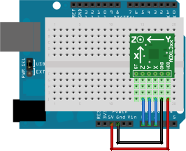
Before start the exercise we will make some tests to see how servos and accelerometer work. In the first example, we need to plug the accelerometer to the Arduino board, using this scheme:
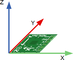
The pins of the accelerometer for power are GND and VDD, so we have to connect them to the board at GND and VDD at 5V. Pins Z, Y and X must be plugged at analog 0, 1 and 2 respectively. These ones correspond to the three-dimensional coordinate axes ZYX (Z height, Y depth and X width) as you can see printed on it. The diagram below will clarify this concept:
The values given by the sensors of the accelerometer of every axis vary from 446 to 576 aprox. This means: if we take the board horitzontally like we have it in the previous scheme (leaving the USB jack at left, and the accelerometer at right) and we turn it clockwise 90 degrees (until jack its looking up and the accelerometer down) the Y axis give us its minimum vale and should be above 446. If we reverse the movement (jack down, accelerometer up) it reaches his maximum value and give us 576 aprox. The X axis did not changed almost in this process, and if the board is parallel to the ground, it will give us a value of 511 aprox. Next we have a little theoretical calculation of this value:
576-446 = 130
130: 2 = 65
576-65 = 511 (or 446 + 65 = 511)
In the exercise the first thing to do it's "calibrate" these values, so we gonna store these values in two variables. In this exercise we don't need the Z axis value. The calibration must be done with the board vertically, leaving the USB up and the accelerometer down.
We need to create two variables (yAxis and xAxis) to store the values of Y axis (analog 2) and X axis (analog 3). Y axis will reach its minimum value (446), so this will be the value to subtract. We will do the same in the X axis subtracting the value intermediate (511), as will be parallel to the ground.
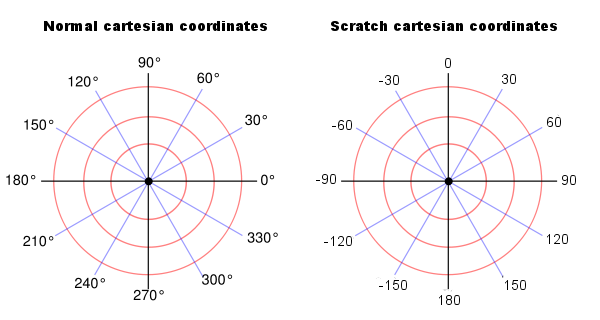
For what we need every axis? As we know the coordinate system of Scratch in regarding the direction of an object varies somewhat with respect to normal:
So we are gonna use the X axis tocontrol the threshold 0, to know when switch between negative to positive and Y axis to vary the direction of the object. As the value of the Y axis does not match with the direction of a Scratch object, we must do a small conversion: if we turn the board to the right we see that the variable Y takes a value About 65 (which it confirms the calculation we have done before) and in Scratch right equals 90, so:
90 / 65 = 1.384615385 (1.4 rounding up)
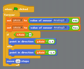
This is the factor that we use to pass the value of the Y axis in the direction of Scratch. Please note that this factor is valid when the value of X axis is greater than 0, ie, when the board pointing to the right. If that points to the left, we will use the same factor but negative:
We also added a block to move the object.
Example 2: Robot Controled with keyboard
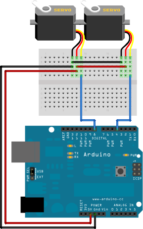
In the following example we will control the robot with the keyboard. The assemble scheme will be the following:
We need to connect each servo at (5V) and to the ground (GND) and one connected to the pin 4 and the other to the pin 7, they will recive the signal form the board and the program.
When we got it, we can start to program. first we have to create a new project, (File> New)put two blocs of motors and then we select the pins where we have it connected:
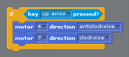
Putting one in clockwise and the other counterclockwise and we start them making doble click on them, the robot should move forward (or backward depending of the order we plugged the servos). If we want to move it when we push a key we should do the follow:
Now we have to do the same for the other keys, (changing the direction of each engine). And adding the Space Key for Stop the robot:
If we want the robot move when we push a key, and stop when we don't touch the keyboard we can do and alternative version:
Example 3: Robot Controlled with and accelerometer
Now, we know how accelerometer and robot works, so we are ready for do the last exercice: Control the robot with the accelerometer.
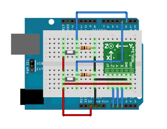
The first we need its add two switches (botons) to the accelerometer board, like this:
One of these switch it's for start and stop the robot, and the other for switch between forward and backward movement. Everyone requires a resistor of 10k acting as a pull down.
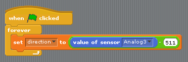
Now we can start to "Build" the program. We gonna start with the accelerometer board. The first step will be calibrate the acclerometer, like we did in the first exemple, but this time the only axis we need its X. How we got it plugged at Analogic pin 2 we gonna use analog 3. And we create a new Variable, (for all the other objects, because we gonna need to see them from arduino obect) where we gonna store the X axis value calibrated:
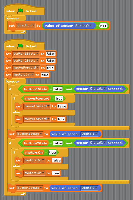
This variable "direction" will give us 0, aproximately, when we got the board vertically with the usb cable pointed up.
The next step its create another bloc of instruccions for control the state of the bottons; We will create a few variables (only for this Object) to keep the button state. Also create two variables, one to know when the robot is started or stopped (motorsOn) and one for controlling the movement forward and backward (moveForward). The latter must be for all objects.
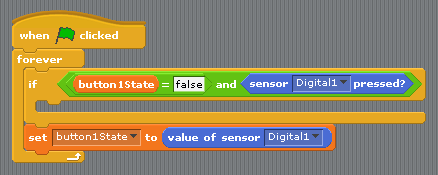
But the fact of using buttons raises a question: for example, in the case that control the movement forward or backward, we want to change direction only when you press the button or you continue until you give again? Obviously the second option is more practical (and also more complicated, though not much). Therefore, we will move only when it detects when you press the button, that is, if we were not pressed the (false) to down (true). In addition we will update the status of the button depending on whether or not the button is pressed:
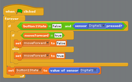
By this way if u press and hold the button, only goes one time to the conditional. because when it comes out, assing the value Digital1 (true) button1State to the variable, and repeats the loop when the condition is not met button1State as is true and not false. Now you should add what the condition has to do:
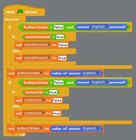
Now when it comes to conditional, will look the value of the variable moveForward. In case of that is true it will change to false and vice versa. So every time you press the button will shift from one sense to another. We do the same with the power button and the variable motorsOn and put it together with what we have:
Now all that remains is initialize the variables and we will have the board with the accelerometer:
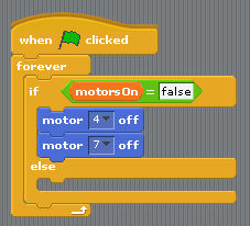
The following is create a new Arduino object for the robot. Here all you do is check the value of the variables motorsOn, moveForward and direction and act accordingly. For example, if the variable motorsOn is false means that the robot is stationary. Otherwise it means to be moved:
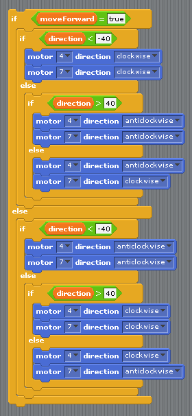
And what we have to do when the engines are running? Directing them as the variables moveForward and direction. With the latter we choose one threshold value to know when we turn right, left or go straight ahead (for example we can use one value of 40 approximately). Then we will have three cases:
if direction is less than -40: turn left.
if direction is greater than 40: turn right.
if not met any of the previous two (ie, direction is between -40 and 40): go straight.
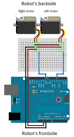
Before starting we must stipulate what is the front and back of the robot to know when to go forward or back and what engine is for the right and wich is for left. In our case we designed this way:
The left engine is connected to pin 4 and right engine at pin 7. Below we have a table that summarizes in what sense should be the engines depending on the value of and direction in the case of the robot go forward, that is, when it meets moveForward is true:
| value of direction | type of movement | left servo (pin 4) | right servo (pin 7) |
| less than -40 | turn left | clockwise | clockwise |
| more than -40 | turn right | anticlockwise | anticlockwise |
| between -40 and 40 | go forward | anticlockwise | clockwise |
In the case of "moveForward" its false, its the same but reversed:
| value of direction | type of movement | left servo (pin 4) | right servo (pin 7) |
| less than -40 | turn left | anticlockwise | anticlockwise |
| more than -40 | turn right | clockwise | clockwise |
| between -40 and 40 | go forward | clockwise | anticlockwise |
Now the only thing to do its apply that to our program:
And add it to what we had done:
Enjoy! :)
Example 2: Script music workshop (Kandinsky)
Needed components:
1 x Arduino board: http://www.sparkfun.com/products/9950
1 x Sensor infrared SHARP GP2Y0A21YK: http://www.sparkfun.com/products/242
1 x LED RGB: http://www.sparkfun.com/products/105
1 x usb cable: http://www.sparkfun.com/products/512
Step 1: Playing notes with the sensor
Before anything else Create an Arduino object (or take what comes by default at the beginnig of new project), which set one number to a variable depending on the value of the sensor
How we have to constantly monitor the value of the sensor we will use one endless loop where each iteraction store the value of the sensor into a variable. Depending on the value and if exceed or not certain thresholds, the variable will have one value or another value (from 1 to 7). In case of it is less than 160 (that is, if the sensor does not detect any obstacle) consider one value of 0. Note: The variable value must be visible to all items!
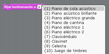
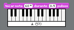
We will create another Object that will be the main program. What what we have to do first is to choose an instrument. If you click at the block "set instrument to" a dropdown list must show with different types of instruments. Just memorize which number corresponds to:
The notes can also viewed at block "play note <> during <> pulse":
Now we will create a new variable where we store the number of instrument and another for the note. Then make again an infinite loop where we must change the value depending of the value of variable "value"
Furthermore, if this is different from 0, and thus the value of the sensor is greater than 300, send a message playNote:
This part can be done on stage. When receives the message playNote, will set the instrument we have chosen and will play the corresponding note for a time. This process is repeated each time the message is relayed:
And with that we can start playing!
Step 2: Record the music
Now that we can play music through Arduino, we store each note on a list for when you want to play them. We must avoid touching any note with the sensor while the tune is playing, so we gonna use a "flag" variable named "playing", for example. In other words, we can only play in real time when playing = 0, ie, when not reproducing the list of notes. Otherwise, when one does not play any notes or stored.
Then create a new object (in this case called PlayButton) to reproduce the melody when you press it with the mouse (the appearance of this object the user can create or take a picture with a built-button "play "or something like that). When this object is pressed, will begin to "search" in the list (with the help of the variable index) and play every note that is saved in this, but not before putting the variable streaming to 1 so that played the main program can not touch or keep any notes, as explained above. When reproduced the whole list, put it back to 0.
Also its needed to put 0 at the start of the program (see capture below)
Step 3: Change the rhythm
If we wanna use the sensor for change the rhythm of the melody, when this one is playing, we gonna use a variable "Tempo", which we gonna modify like the variable "note" (with other values), changing the code of this one and moving it apart:
We can exchange the two parts when we are playing or in reproducing mode. For modify the tempo in real time, we need to do the following: (we can do it directly in the escenary)
Step 4: Erase the Melody
For finish we are going to create another object for erase/delete the melody, when this one it's pressed:
Step 5: Record Button
If we don't want the program to save automatically the notes that we are playing, we can make an additional button for recording control (like the "Rec" option of any media device). The main purpose of this is to change the variable named "Record" from 0 to 1 and viceversa:
And when we are going to use this variable? At the main program, where we play the note depending of the value of the sensor:
And that's all!
